Scope and common interpretation errors
For tooling-process reviews by qualified personnel; no universal vent dimensions are supplied.
Blocked venting and excessive local gaps may coexist. Dirt and clamp condition also matter; enlarging every vent can spread a local problem.
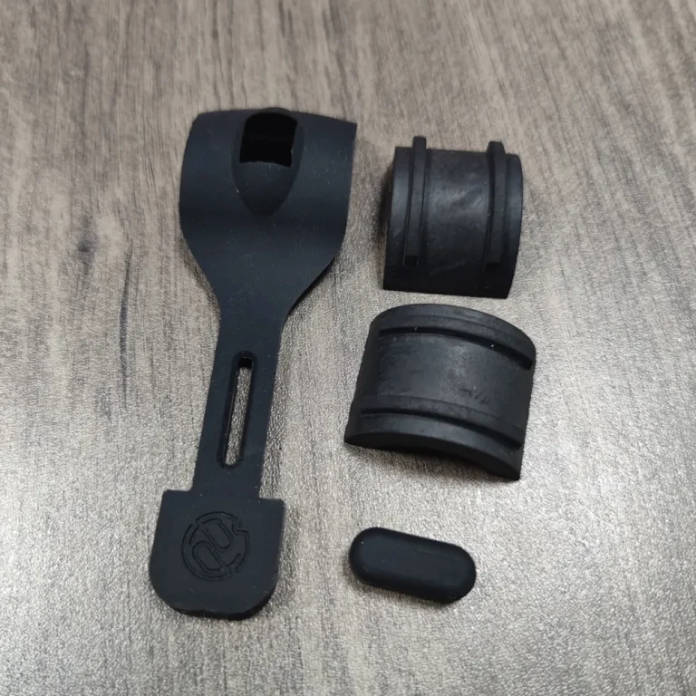
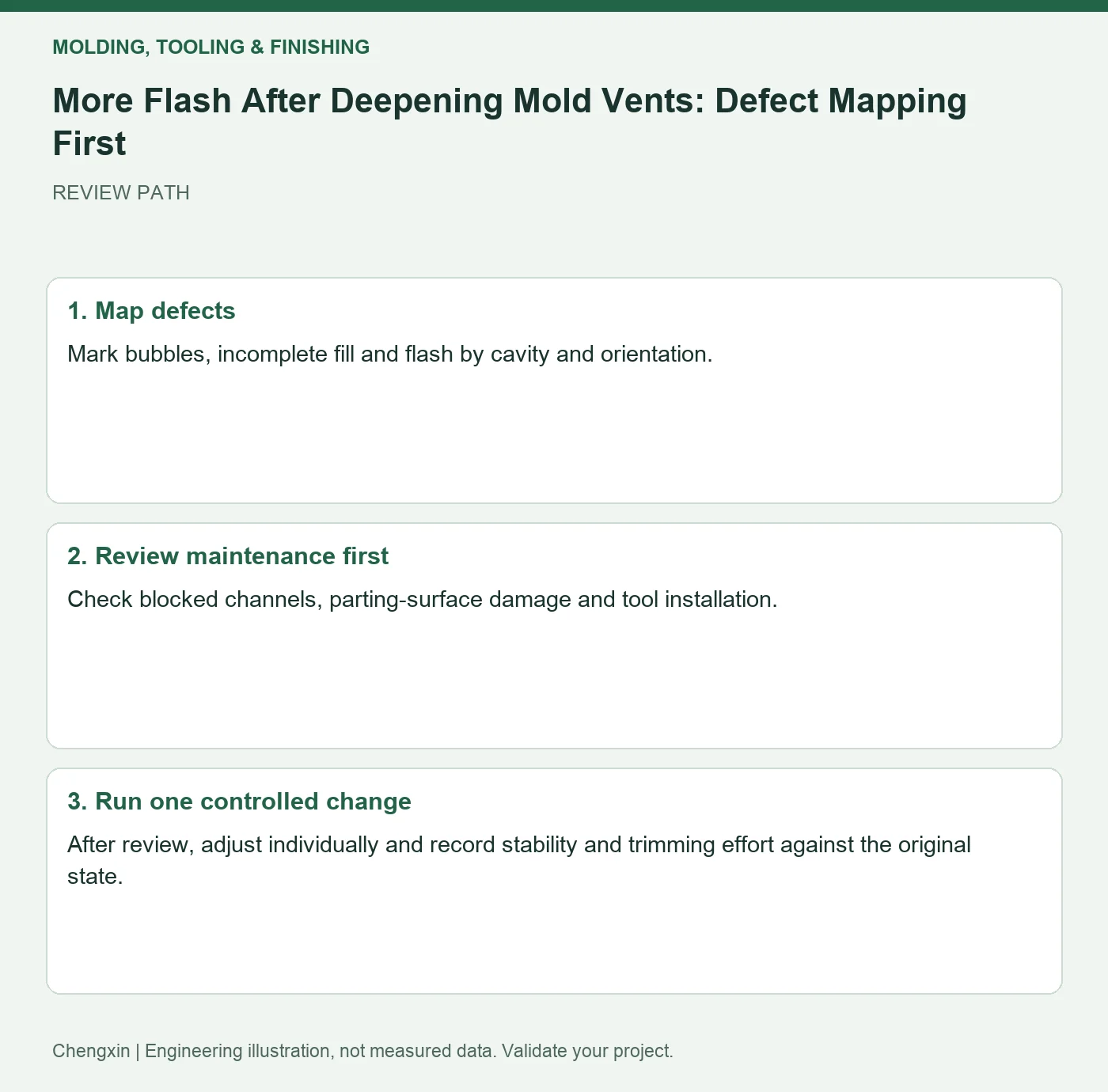
Turn the review into recorded checks
| Step | Action and evidence |
|---|---|
| 1 · Map defects | Mark bubbles, incomplete fill and flash by cavity and orientation. |
| 2 · Review maintenance first | Check blocked channels, parting-surface damage and tool installation. |
| 3 · Run one controlled change | After review, adjust individually and record stability and trimming effort against the original state. |
A comparison to avoid misinterpretation
Bubbles only at the flow end with flash elsewhere call for local airflow analysis, not a simultaneous all-round vent change.
Frequently asked question
Does more venting guarantee no bubbles?
Raw material, filling and cure conditions still need checks.
Background and further reading
This note addresses one specific question. For broader concepts, see the related background guide.
Related question: Gate Vestiges on Silicone Sealing Faces: Location and Trimming.
External references support the relevant concepts. The review steps and scenarios are independent engineering discussion guidance, not quotations from a standard or external organization. Use agreed methods, applicable document revisions and complete conditions.
Apply this to your custom part
Compare the structure with Custom Shaped Silicone Parts. Describe the application, geometry, operating conditions, quantity and problem to solve. Submit a custom-parts inquiry, or see how to send drawings and sample photographs by business email. Confirm material, dimensions, costs, testing and delivery requirements for the project.