Scope and common interpretation errors
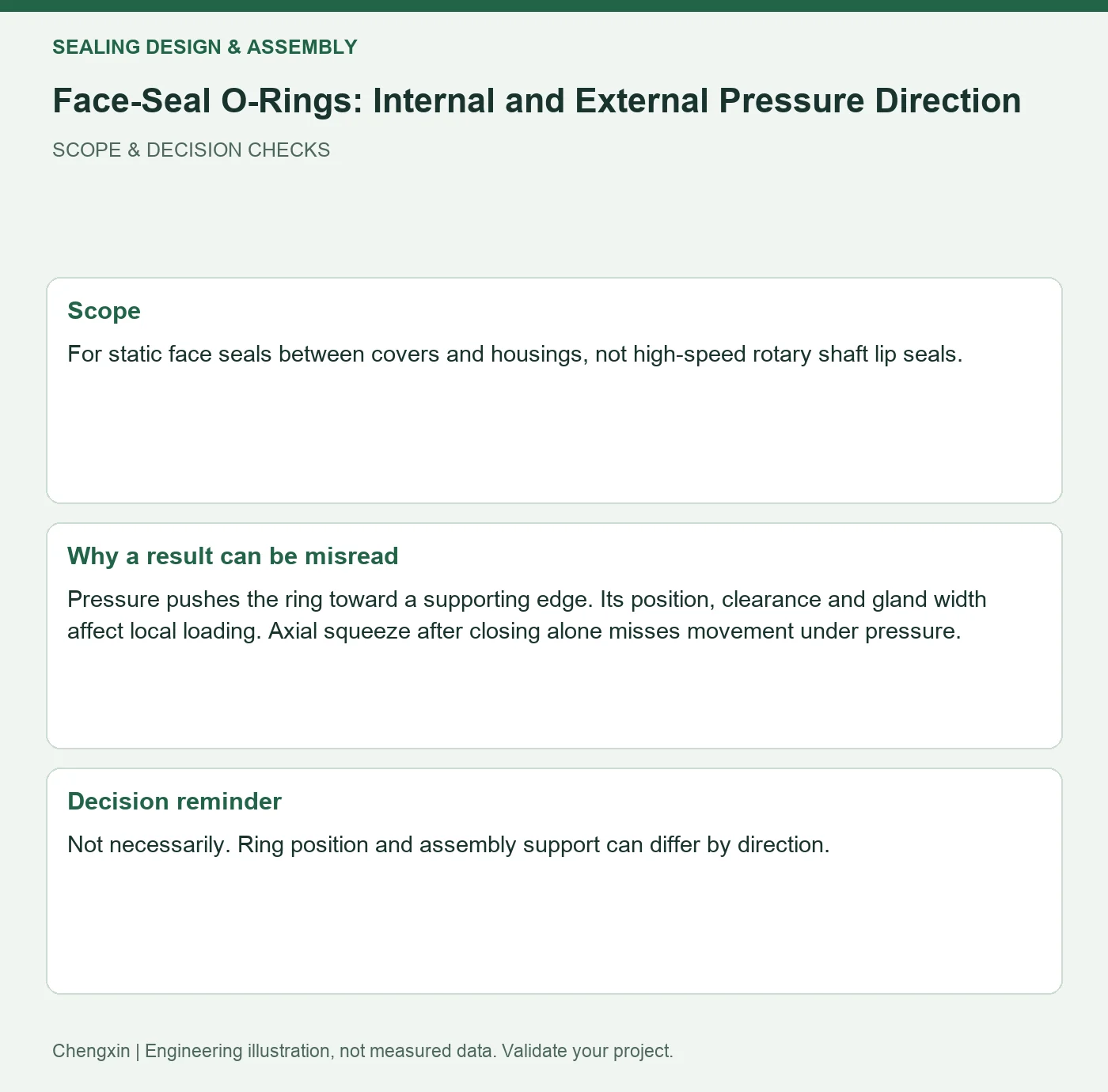
For static face seals between covers and housings, not high-speed rotary shaft lip seals.
Pressure pushes the ring toward a supporting edge. Its position, clearance and gland width affect local loading. Axial squeeze after closing alone misses movement under pressure.
Turn the review into recorded checks
| Step | Action and evidence |
|---|---|
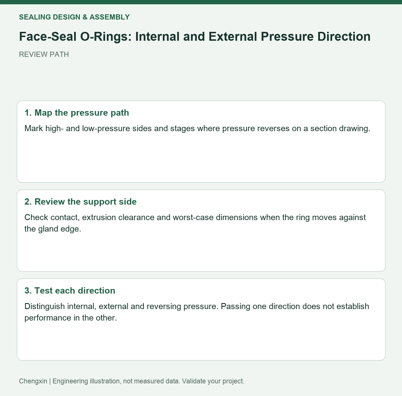
| 1 · Map the pressure path | Mark high- and low-pressure sides and stages where pressure reverses on a section drawing. |
| 2 · Review the support side | Check contact, extrusion clearance and worst-case dimensions when the ring moves against the gland edge. |
| 3 · Test each direction | Distinguish internal, external and reversing pressure. Passing one direction does not establish performance in the other. |
A comparison to avoid misinterpretation
For equipment with vacuum operation and positive-pressure cleaning, first assess both pressure directions separately before deciding whether to share a seal design.
Frequently asked question
Is testing only the largest absolute pressure difference enough?
Not necessarily. Ring position and assembly support can differ by direction.
Background and further reading
This note addresses one specific question. For broader concepts, see the related background guide.
Related question: Seal Parting Lines: Keeping Flash Away from Contact Bands.
External references support the relevant concepts. The review steps and scenarios are independent engineering discussion guidance, not quotations from a standard or external organization. Use agreed methods, applicable document revisions and complete conditions.
Apply this to your custom part
Compare the structure with Shaped Silicone Housing Gaskets for Wearable Devices. Describe the application, geometry, operating conditions, quantity and problem to solve. Submit a custom-parts inquiry, or see how to send drawings and sample photographs by business email. Confirm material, dimensions, costs, testing and delivery requirements for the project.