Scope and common interpretation errors
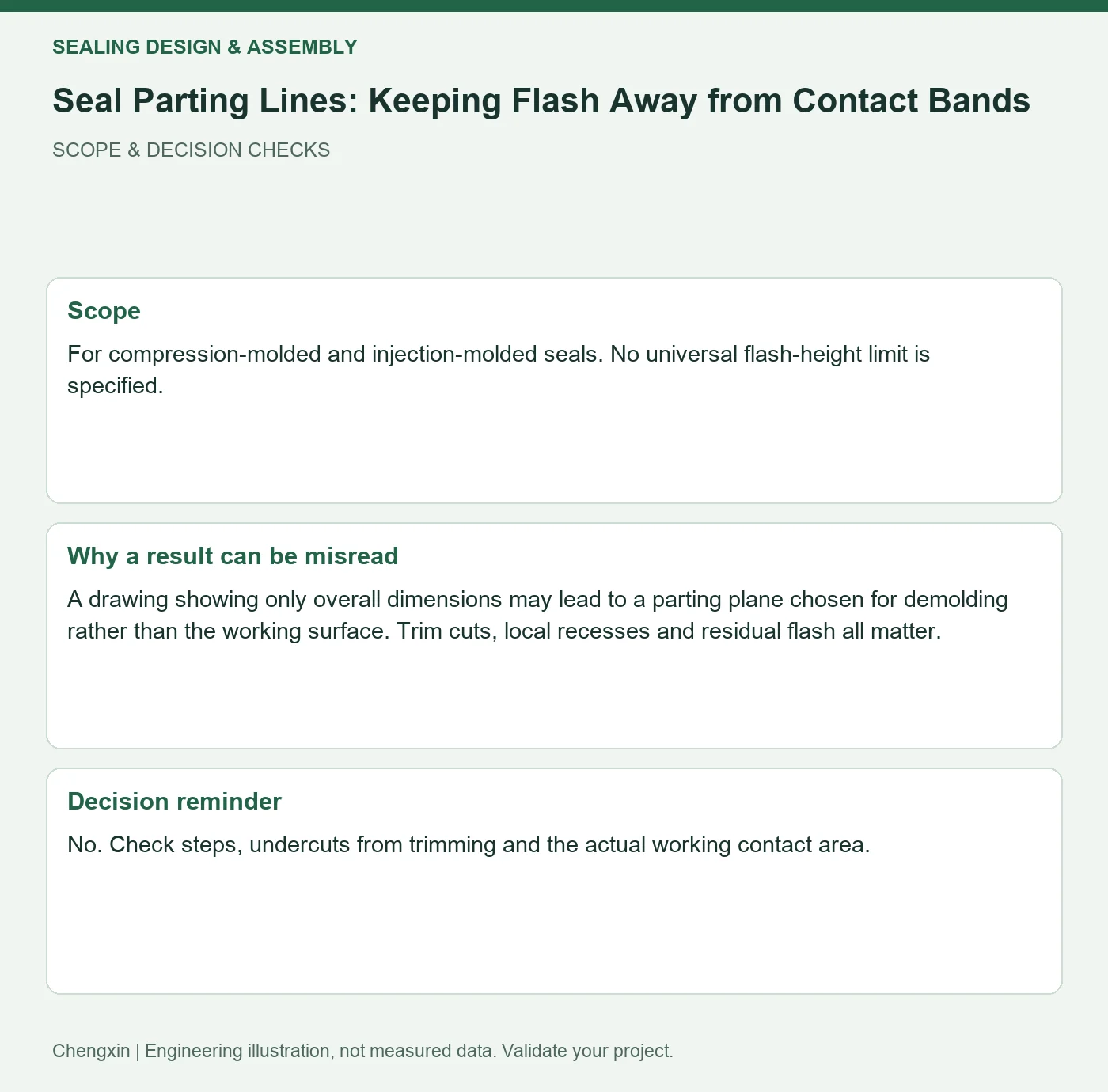
For compression-molded and injection-molded seals. No universal flash-height limit is specified.
A drawing showing only overall dimensions may lead to a parting plane chosen for demolding rather than the working surface. Trim cuts, local recesses and residual flash all matter.
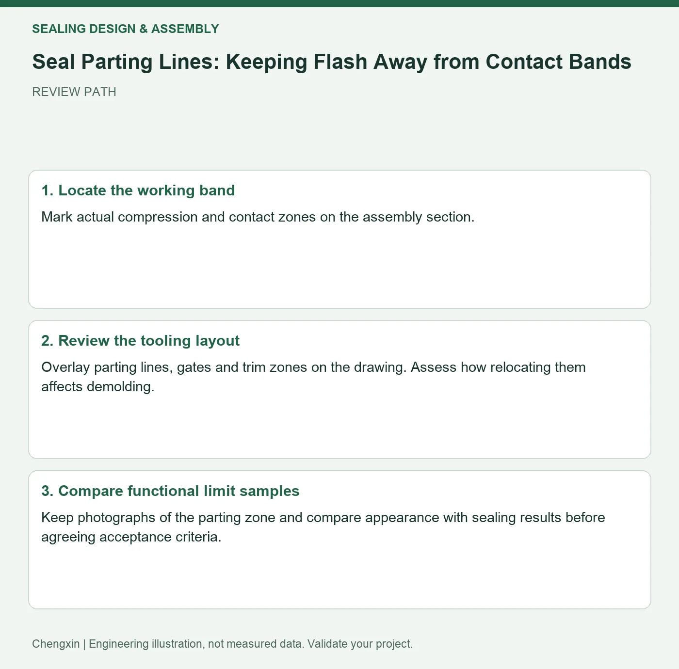
Turn the review into recorded checks
| Step | Action and evidence |
|---|---|
| 1 · Locate the working band | Mark actual compression and contact zones on the assembly section. |
| 2 · Review the tooling layout | Overlay parting lines, gates and trim zones on the drawing. Assess how relocating them affects demolding. |
| 3 · Compare functional limit samples | Keep photographs of the parting zone and compare appearance with sealing results before agreeing acceptance criteria. |
A comparison to avoid misinterpretation
Identical flash on a noncontact side and across a sealing band can have different functional risks. Limit samples should identify location as well as dimensions.
Frequently asked question
Can a parting line be ignored if no obvious flash is visible?
No. Check steps, undercuts from trimming and the actual working contact area.
Background and further reading
This note addresses one specific question. For broader concepts, see the related background guide.
Related question: Detecting O-Ring Twist During Silicone Seal Installation.
External references support the relevant concepts. The review steps and scenarios are independent engineering discussion guidance, not quotations from a standard or external organization. Use agreed methods, applicable document revisions and complete conditions.
Apply this to your custom part
Compare the structure with Shaped Silicone Housing Gaskets for Wearable Devices. Describe the application, geometry, operating conditions, quantity and problem to solve. Submit a custom-parts inquiry, or see how to send drawings and sample photographs by business email. Confirm material, dimensions, costs, testing and delivery requirements for the project.