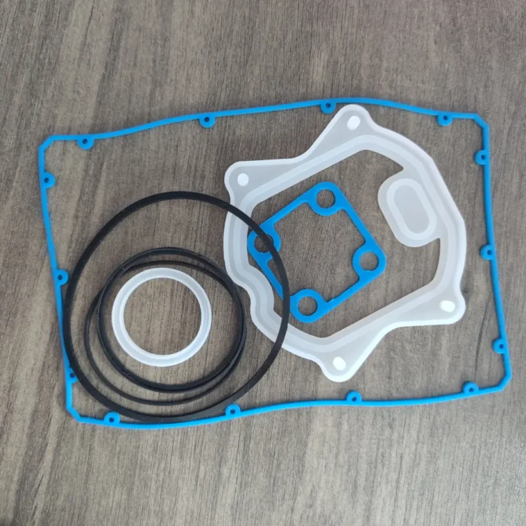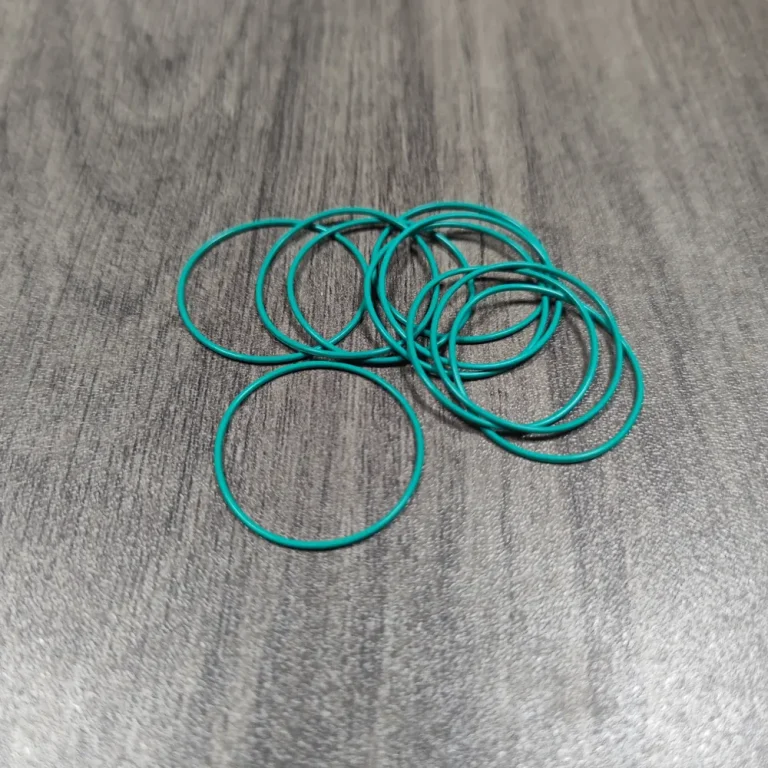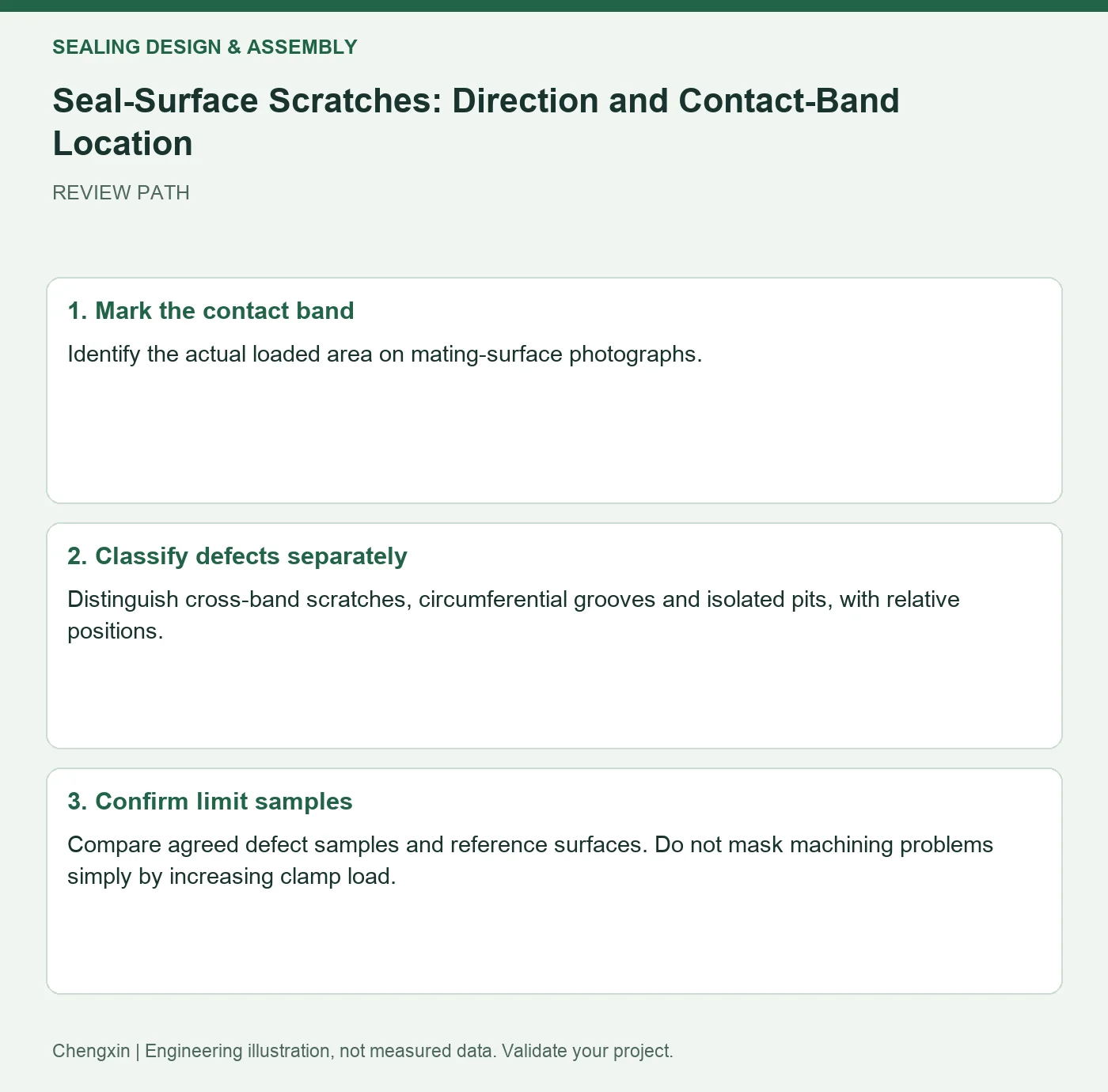
Scope and common interpretation errors
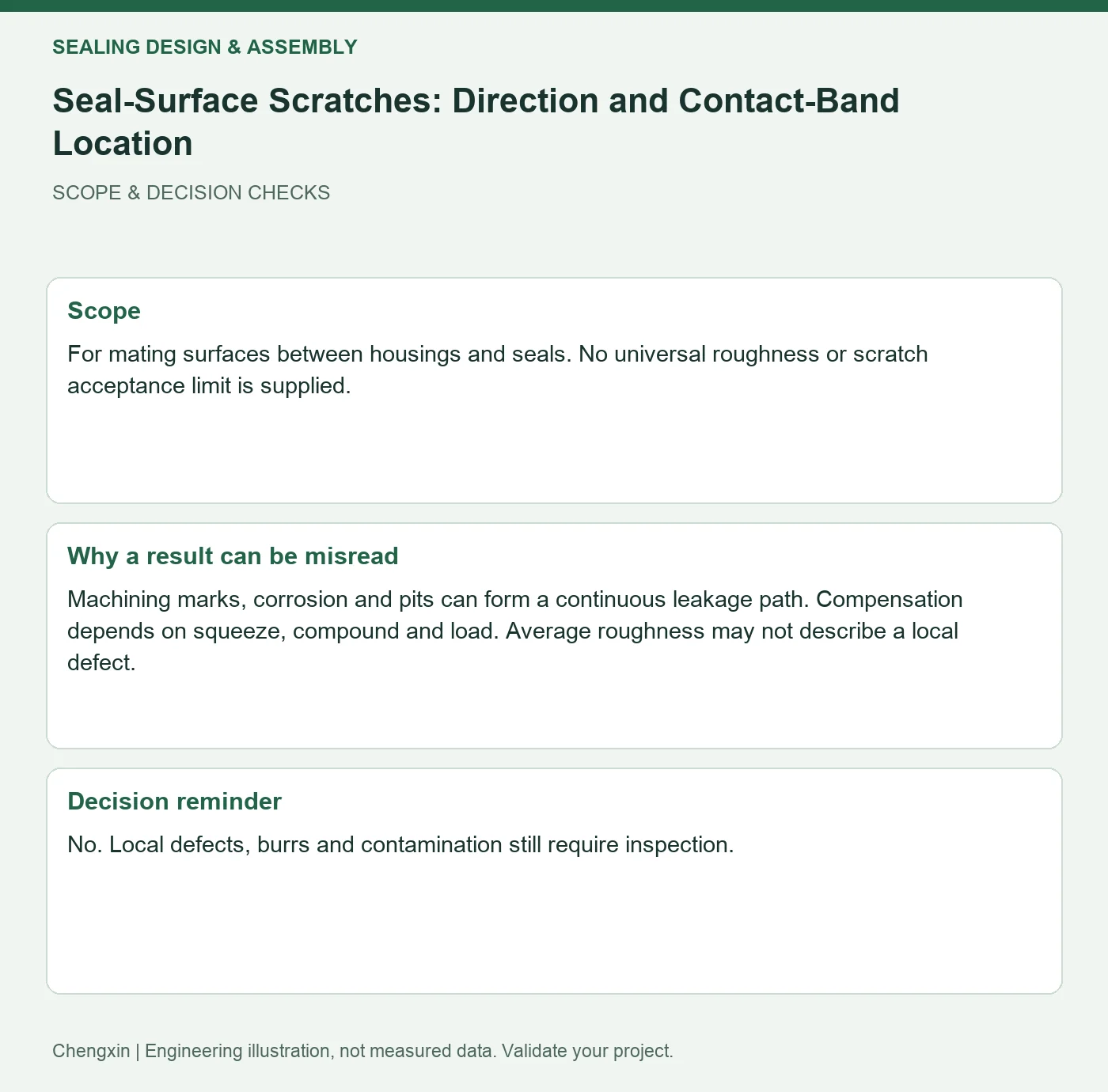
For mating surfaces between housings and seals. No universal roughness or scratch acceptance limit is supplied.
Machining marks, corrosion and pits can form a continuous leakage path. Compensation depends on squeeze, compound and load. Average roughness may not describe a local defect.
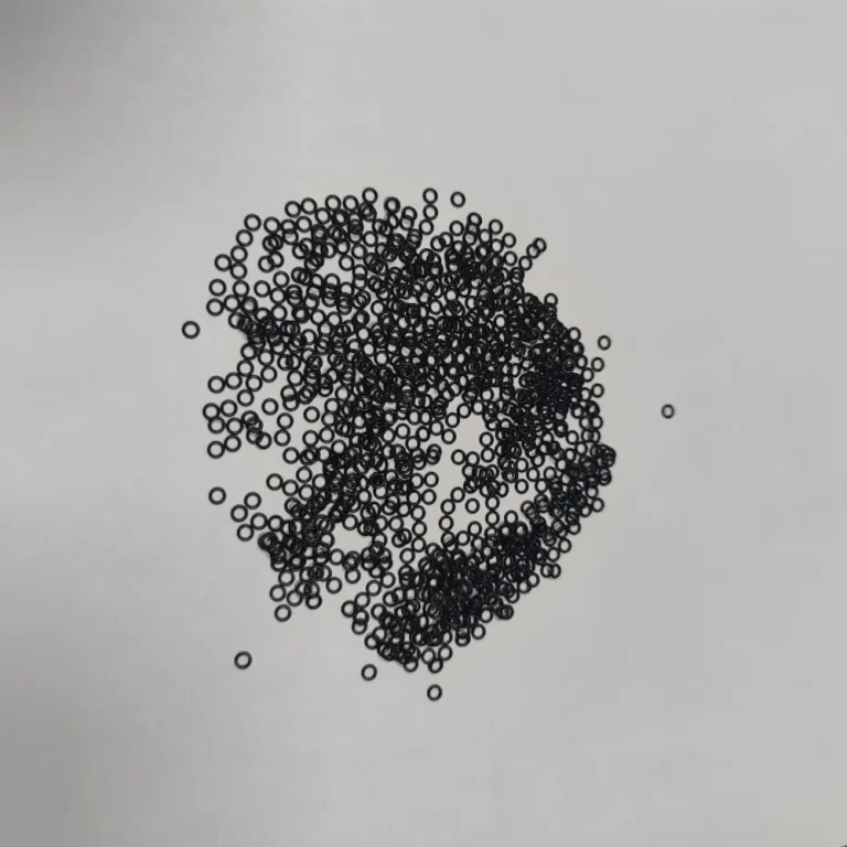
Turn the review into recorded checks
| Step | Action and evidence |
|---|---|
| 1 · Mark the contact band | Identify the actual loaded area on mating-surface photographs. |
| 2 · Classify defects separately | Distinguish cross-band scratches, circumferential grooves and isolated pits, with relative positions. |
| 3 · Confirm limit samples | Compare agreed defect samples and reference surfaces. Do not mask machining problems simply by increasing clamp load. |
A comparison to avoid misinterpretation
A short cross-band groove may matter more than a long scratch outside contact. Relate magnified photographs to leak coordinates instead of recording only 'minor scratch'.
Frequently asked question
Does a passing roughness report remove the need for inspection?
No. Local defects, burrs and contamination still require inspection.
Background and further reading
This note addresses one specific question. For broader concepts, see the related background guide.
Related question: Bulging Corners on Silicone Seal Frames: Radius and Assembly Checks.
External references support the relevant concepts. The review steps and scenarios are independent engineering discussion guidance, not quotations from a standard or external organization. Use agreed methods, applicable document revisions and complete conditions.
Apply this to your custom part
Compare the structure with Precision Silicone O-Rings for Watches. Describe the application, geometry, operating conditions, quantity and problem to solve. Submit a custom-parts inquiry, or see how to send drawings and sample photographs by business email. Confirm material, dimensions, costs, testing and delivery requirements for the project.