Scope and common interpretation errors
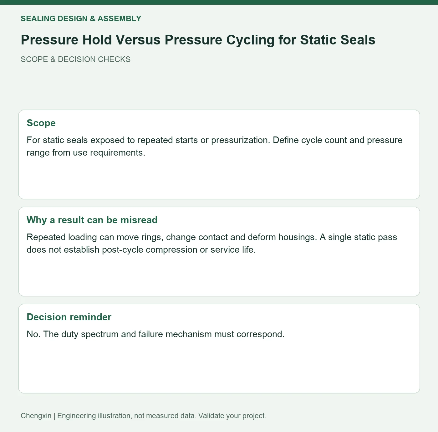
For static seals exposed to repeated starts or pressurization. Define cycle count and pressure range from use requirements.
Repeated loading can move rings, change contact and deform housings. A single static pass does not establish post-cycle compression or service life.
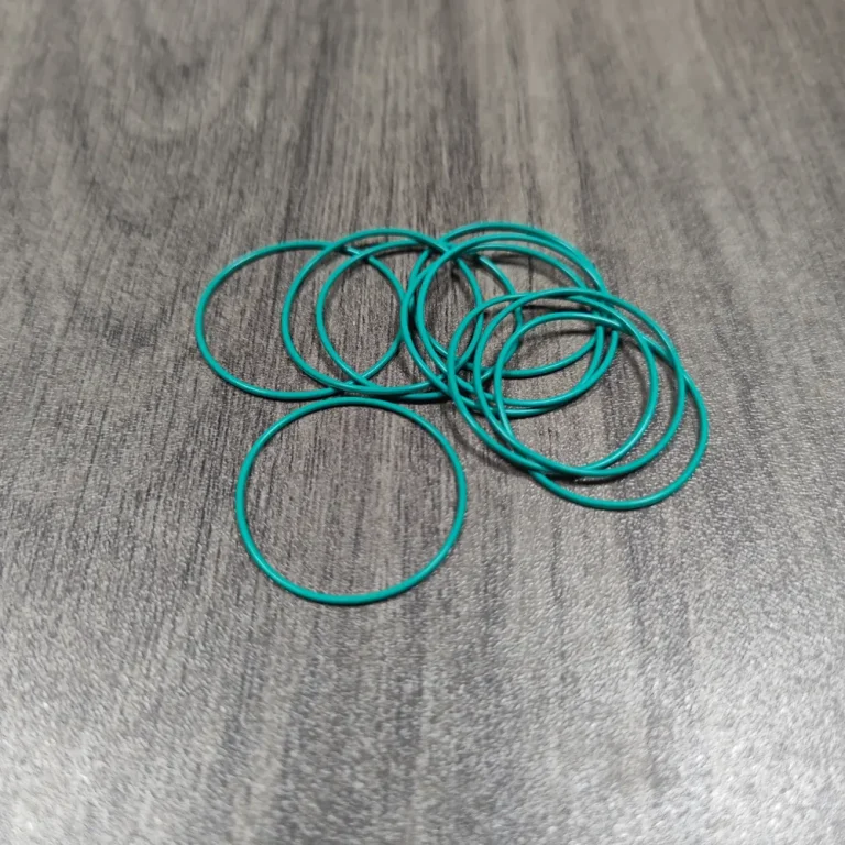
Turn the review into recorded checks
| Step | Action and evidence |
|---|---|
| 1 · Reconstruct service loading | List pressure direction, ramp rates, holds and rest periods. |
| 2 · Plan intermediate checks | Compare initial, intermediate and final leakage, shape and retention. |
| 3 · Review trends before changing parts | Separate sudden leakage, gradual changes and instrument drift; inspect specimens when needed. |
A comparison to avoid misinterpretation
If initial and final readings pass but a transient anomaly appears during cycling, preserve and reproduce that stage rather than reporting only the final value.
Frequently asked question
Does doubling test cycles double promised service life?
No. The duty spectrum and failure mechanism must correspond.
Background and further reading
This note addresses one specific question. For broader concepts, see the related background guide.
Related question: Silicone O-Ring Gland Fill: Allowing for Expansion and Swell.
External references support the relevant concepts. The review steps and scenarios are independent engineering discussion guidance, not quotations from a standard or external organization. Use agreed methods, applicable document revisions and complete conditions.
Apply this to your custom part
Compare the structure with Rubber O-Rings for Cleaning-Equipment Water Circuits. Describe the application, geometry, operating conditions, quantity and problem to solve. Submit a custom-parts inquiry, or see how to send drawings and sample photographs by business email. Confirm material, dimensions, costs, testing and delivery requirements for the project.