Scope and common interpretation errors
For compression- and injection-molded silicone demolding reviews, without unvalidated release-agent advice.
Undercuts, sharp corners and grip points change release loads. Insufficiently stabilized areas may be vulnerable; separate operator and cavity effects.
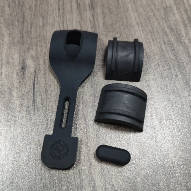
Turn the review into recorded checks
| Step | Action and evidence |
|---|---|
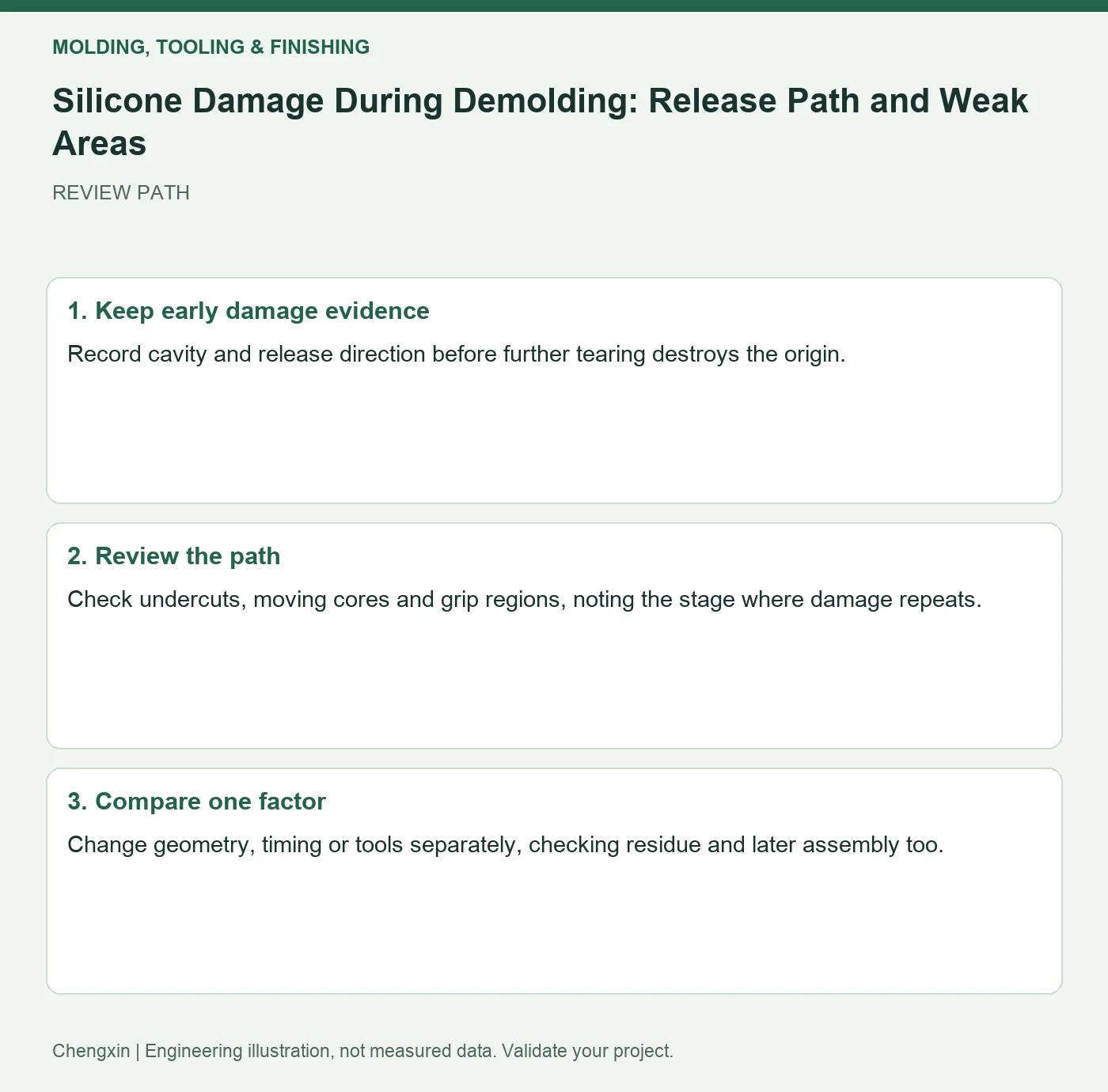
| 1 · Keep early damage evidence | Record cavity and release direction before further tearing destroys the origin. |
| 2 · Review the path | Check undercuts, moving cores and grip regions, noting the stage where damage repeats. |
| 3 · Compare one factor | Change geometry, timing or tools separately, checking residue and later assembly too. |
A comparison to avoid misinterpretation
Damage confined to gripping a thin tab suggests reviewing grip and release order before raising hardness globally.
Frequently asked question
Will more release agent solve the issue?
It may affect surfaces and bonding; check permission and root cause first.
Background and further reading
This note addresses one specific question. For broader concepts, see the related background guide.
Related question: Where to Put Silicone Cavity Numbers: Traceability and Function.
External references support the relevant concepts. The review steps and scenarios are independent engineering discussion guidance, not quotations from a standard or external organization. Use agreed methods, applicable document revisions and complete conditions.
Apply this to your custom part
Compare the structure with Custom Shaped Silicone Parts. Describe the application, geometry, operating conditions, quantity and problem to solve. Submit a custom-parts inquiry, or see how to send drawings and sample photographs by business email. Confirm material, dimensions, costs, testing and delivery requirements for the project.