Scope and common interpretation errors
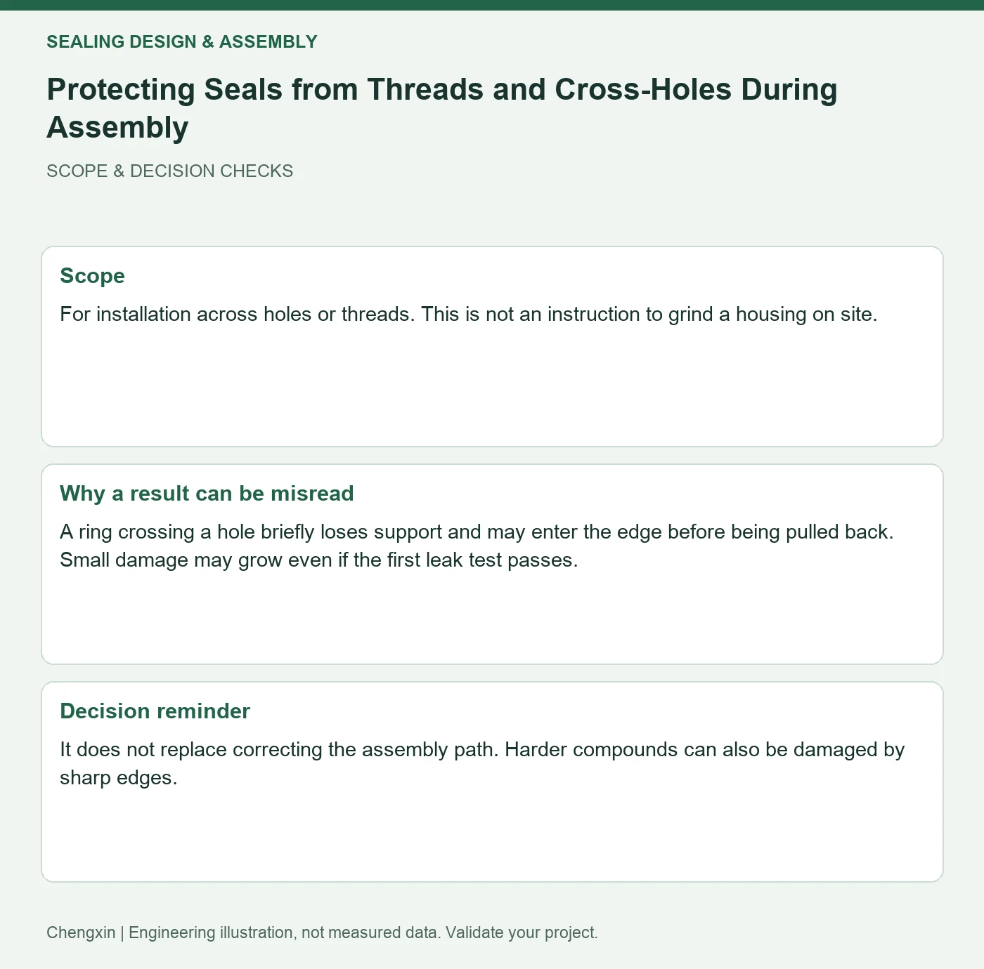
For installation across holes or threads. This is not an instruction to grind a housing on site.
A ring crossing a hole briefly loses support and may enter the edge before being pulled back. Small damage may grow even if the first leak test passes.
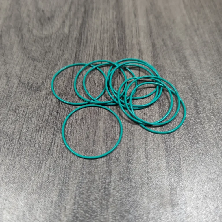
Turn the review into recorded checks
| Step | Action and evidence |
|---|---|
| 1 · Map the full path | Mark openings, joints and steps from insertion point to gland. |
| 2 · Inspect the protective sleeve | Check coverage, smooth joints, material compatibility and cleanliness so the tool introduces no new sharp edge. |
| 3 · Inspect removed specimens | Compare marks and sealing with and without a sleeve on dedicated samples. Do not deliver specimens after destructive disassembly. |
A comparison to avoid misinterpretation
Compare magnified photographs of specimens assembled with and without a sleeve. Relate damage orientation to the position of the cross-hole.
Frequently asked question
Will higher rubber hardness prevent cutting?
It does not replace correcting the assembly path. Harder compounds can also be damaged by sharp edges.
Background and further reading
This note addresses one specific question. For broader concepts, see the related background guide.
Related question: Gasket Compression Stops: Separating Closure from Screw Torque.
External references support the relevant concepts. The review steps and scenarios are independent engineering discussion guidance, not quotations from a standard or external organization. Use agreed methods, applicable document revisions and complete conditions.
Apply this to your custom part
Compare the structure with Rubber O-Rings for Cleaning-Equipment Water Circuits. Describe the application, geometry, operating conditions, quantity and problem to solve. Submit a custom-parts inquiry, or see how to send drawings and sample photographs by business email. Confirm material, dimensions, costs, testing and delivery requirements for the project.